Liquid Crystal Technology
What is Liquid crystal?
In the time since an Austrian botanist named Friedrich Reinitzer discovered that some materials have a middle phase between solid and liquid in 1888, Liquid Crystals, as these materials were to be called, found a wide range of applications from basic scientific research to consumer electronics.
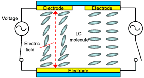
Figure 1 shows LC device structure. Liquid Crystal (LC) molecules are shaped like rods for which each position is random, although the direction of the rods is regularly-arranged parallel to their long axis. The molecules have a dielectric anisotropy and align with the long axis parallel to the direction of and applied electric field. Today, this characteristic is utilized as the ON/OFF light switch for displaying an image in LC projectors and displays.
Santec LC technology
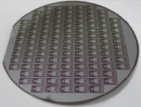
Santec has developed and manufactured LC devices as one of our core technologies for advanced optical devices and systems, as shown in Figure 2.
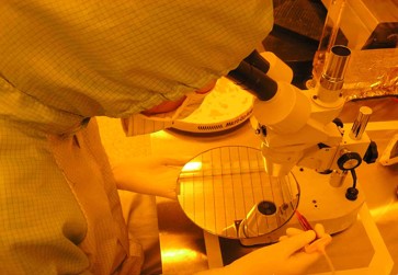
The mass production line consists of an 8 inch wafer process. Santec LC devices are characterized by a wide viewing angle, high contrast ratio and high reliability resulting from adopting vertically aligned nematic (VA) mode and inorganic LC alignment layer. Some examples are shown as below.
LCOS spatial light modulator
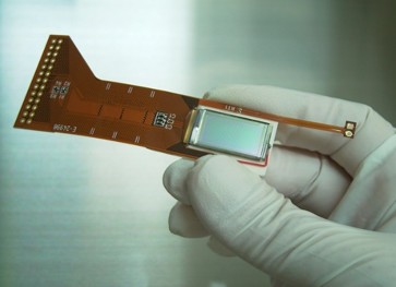
LCOS is a micro-display and micro-projection technology for LC projector and rear-projection TV. LCOS is normally reflective type LC panel consisting of reflective layer and LC on Si substrate. Figure 3 shows an example of LCOS device. Switching elements and electric wires for driving LC are integrated on Si substrate under reflective layer with semiconductor manufacturing technology and the image is characterized by seamless and high pixel resolution.
We have developed an unique LCOS device for a variety applications including fiber-optics using proprietary LC materials.
LCOS performance (phase modulation scheme)
1. Phase shift (φ)
Maximum phase shift of 2π rad at 1550 nm is available. Figure 4 shows tphase performances in (a)π rad and (b)2π rad in an user setting. Users can choose π rad mode or 2π rad phase shift mode by adjusting the drive parameters. Santec’s high resolution LCOS device shows an excellent phase linearity without a LUT (look-up-table) option on the driver board. LUT is also available as an option.
Figure 4. Phase shift performances in (a) π rad, (b) 2π rad

Figure 4 (a)

Figure 4 (b)
LC device for fiber-optics
A change of LC dielectric constant anisotropy along with applied electric field enables the control of optical phase and amplitude freely. Santec has developed various optical components and test instruments utilizing the LC controllability for advanced optical communication networks. Santec LC devices are Telcordia qualified and high reliability is guaranteed in our components and instruments (Figure 7).
The wavelength blocker (WB) is a multi-functional optical module for constructing ROADM (Reconfigurable Optical Add/Drop Multiplexer) nodes in next generation optical networks (Figure 8). The module outputs WDM (Wavelength Division Multiplexing) signals with an arbitrary amplitude or blocking for any WDM channels. Santec WB adopts to reflective type LC devices with segment electrodes corresponding to WDM channel number for optical amplitude control.
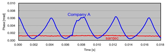
3. Phase stability (Flicker noise)
In general, a phase noise at a video frame rate is generated in a LCOS device. This noise is so called as Flicker noise. Figure 6 shows an example of phase stability. Our LCOS device has designed to minimize the Flicker noise as small as possible for fiber-optic and precision applications. Our LCOS device has achieved better phase stability as small as 0.002 dB, as shown in Figure 6 red line.
光通信用液晶素子
外部電場により誘電率異方性が変化する液晶の特徴を利用すると、光の位相、振幅を自由に制御することが可能です。この制御性に着目し、当社では液晶を応用した各種光通信用部品、測定器の開発を進めております。図7に示す光通信用液晶素子はTelcordia規格に準拠した優れた信頼性を有しております。
図8に示す波長ブロッカーは次世代光ネットワークのROADM(Reconfigurable optical add/drop multiplexer)ノードを構成するための光機能モジュールです。入力されたそれぞれの多波長光信号を任意の強度で出力、もしくは遮断する機能を有しており、光強度制御に光信号波長数に相当する数のセグメント電極を持つ反射型液晶素子を使用しています。

Figure 8. Wavelength blocker (a) Product outlook, (b) LC device

Figure 8. Wavelength blocker (c) Example of wavelength selected spectra
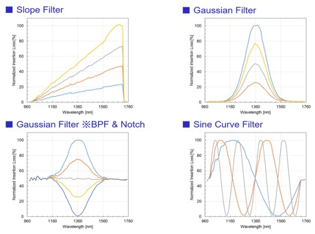
Spectrum controllable tunable filters with LCOS technology that enables an arbitrary optical spectrum. The filter allows you to design any complex optical filters for next generation optical communication networks, which were difficult to realize with conventional filter technologies. Figure 9 shows arbitrary spectra. The pixel pitch, width and number of LCOS chip are 5 µm, 4.7 µm and 2560 µm, respectively. And 12 bit level of LC driving voltage makes high spectrum control resolution possible.